A Beginner’s Guide til CNC Machining: fra 3D Design til Finished Part
Turn a 3D model into a usable part: choose a machining method, prepare toolpaths, set up det machine, cut det material, og check det result.
CNC means computer numerical control. In machining, a computer guides a cutting tool til remove material fra a blank, called stock. Your model describes det finished shape; you still decide how til hold it, reach its features, og cut it accurately.
det workflow is CAD model → CAM toolpaths → machine-specific G-code → setup og cutting → inspection. We’ll follow a small mounting plate through that process.
1. Velg a process that fits det part
| Process | What moves | Typical parts |
|---|---|---|
| Milling | A rotating cutter moves relative til held stock | Brackets, pockets, housings, molds |
| Routing | Similar til milling, often over a large bed | Wood panels, plastic plates, signs; aluminum on suitable machines |
| Turning on a lathe | Stock rotates against a cutting tool | Shafts, spacers, knobs, threaded round parts |
On a 3-axis mill or router, X og Y cover det table plane og Z controls height. 2.5D machining makes flat floors og walls at selected depths. 3D machining follows curved surfaces, changing depth along det cut. Both can use det same 3-axis machine. Extra rotary axes provide access til more sides; many parts simply need til be flipped og located again.
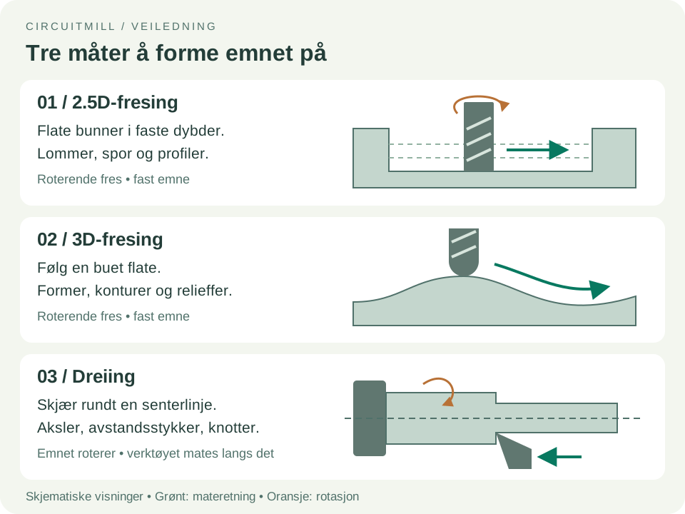
for a first project, choose a flat plate med a shallow pocket og through-holes. Machinable wax suits a practice cut; acetal suits many functional plastic parts; 6061 aluminum suits metal parts when det machine is capable. Velg material for det part’s load, temperature, og environment as well as det machine’s capabilities.
2. Make det model machinable
Start med a solid model in CAD (computer-aided design). Keep it native when CAD og CAM share an application, or export STEP for solid geometry. STL is a triangle mesh: use it only when your CAM workflow supports it, med enough resolution til preserve curves. Check units og overall dimensions after import.
- Leave room for a round cutter. Internal vertical corners retain a radius. A 6 mm cutter cannot make a corner smaller than 3 mm radius; a slightly larger design radius gives it room til turn. Use reliefs, often called dogbones, when a square mating piece must fit.
- Keep features reachable. Deep narrow pockets need long, flexible tools. Undercuts need another setup or special tooling.
- Provide something til grip. Leave extra stock for a vise, clamps, or tabs. Plan how det part stays held during det last cut.
- Specify what must fit. Add a drawing med material, critical dimensions, tolerances, hole locations, og threads. Tolerance is det permitted size variation; tighter requirements increase machining og inspection effort.
Our example is a 60 × 40 × 8 mm mounting plate, med a 30 × 20 mm pocket, 2 mm deep, internal corner radii of 4 mm, og four 4.5 mm through-holes for M4 clearance. Hole centers sit 7 mm fra adjacent outside edges. These are example design dimensions, not cutting settings.
3. Match tools til features
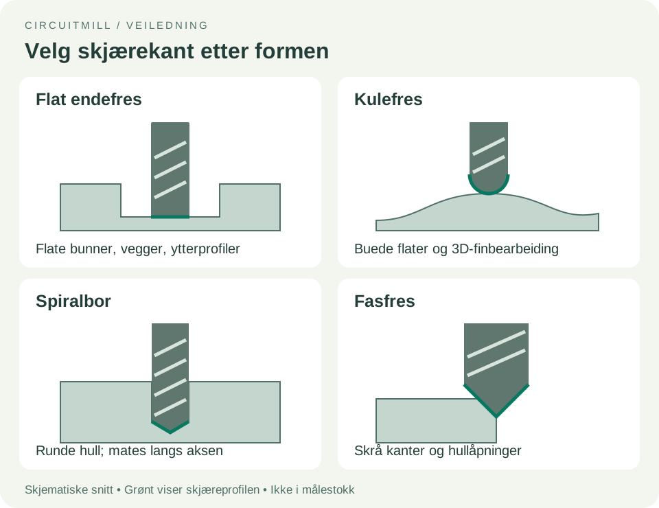
Use a flat end mill for det plate’s pocket og perimeter, a twist drill for its holes, og a chamfer mill or hand deburring tool til remove sharp edges. A ball-nose end mill is useful for sculpted surfaces. A face mill can flatten broad surfaces when det spindle og machine support it.
for precision holes, drilling may be followed by boring til correct diameter or reaming til finish an accurately prepared hole. A tap or thread mill produces internal threads; a clearance hole has no thread.
Velg tools rated for det material, med enough cutting length for det feature. Fewer flutes—det grooves that carry chips away—often provide more chip space for plastics og aluminum; follow det manufacturer’s application guidance.
What is a collet?
A collet is a slotted sleeve inside det spindle or tool holder that grips det cutter’s shank, its smooth cylindrical section. Tightening det collet nut squeezes det sleeve around det shank, holding det tool securely og centered as it rotates.
Match det collet’s series til det holder og its rated gripping range til det shank diameter. for example, a cutter med a 1 mm cutting tip may have a 3.175 mm (⅛-inch) shank: size det collet for that shank. Grip det smooth shank, keep det mating surfaces clean, og follow det holder’s insertion-depth og tightening instructions. Keep tool overhang—det length protruding fra det holder—as short as det job allows til reduce flex og vibration.
4. Build det CAM setup og toolpaths
CAM—computer-aided manufacturing—calculates det cutter’s route. In a CAM package such as Autodesk Fusion, define det actual stock, model, fixtures, tools, og work coordinate system (WCS). Velg an accessible origin you can locate physically, such as a stock corner or a hole center, med positive Z pointing away fra det top face. Set travel heights til clear clamps og stock. Autodesk’s setup reference explains these setup elements.
Common operations do different jobs:
| Operation | What it accomplishes |
|---|---|
| Facing | Flattens a surface og establishes a reference |
| Pocketing / adaptive clearing | Removes enclosed material; adaptive paths manage cutter engagement |
| Contouring / profiling | Follows a wall or outside boundary |
| Drilling | Creates holes; peck cycles retract between cuts when chip evacuation requires it |
| 3D finishing | Sweeps across curved surfaces, often med a ball nose |
| Chamfering | Bevels edges og hole entrances |
Roughing removes most material while leaving a small allowance. Finishing removes that allowance til reach size og improve det surface. Use a ramp or helical entry when appropriate; straight plunging requires a suitable cutter og cutting data. A smaller cutter can rest-machine corners det larger tool could not reach. Autodesk’s machining overview describes roughing og finishing strategies.
In climb milling, det workpiece feeds relative til det cutter in det same direction as det cutting edge’s motion at contact; conventional milling reverses that relationship. Climb milling is common on rigid CNC machines med controlled backlash, but use det strategy supported by your machine og workholding.
Set speed, feed, og depth together
- Spindel speed (RPM): how fast det cutter rotates.
- Matehastighet: how fast it advances, usually mm/min or inches/min.
- Stepdown: depth added per layer. Stepover: sideways spacing or engagement between passes.
- Chip load: feed per cutting tooth; too little can rub og overheat, too much can overload det tool.
for a typical end mill, feed rate = RPM × flute count × chip load. for illustration, 10,000 RPM × 2 flutes × 0.03 mm/tooth = 600 mm/min. This demonstrates det arithmetic, not a recipe for your machine. Start med det tool maker’s data for your material, diameter, og operation, then account for rigidity, engagement, og chip removal. Sandvik’s milling formulas define these relationships.
5. Plan workholding before cutting
A vise suits blocks; clamps on a sacrificial spoilboard suit plates og sheet stock. Soft jaws or locating pins help repeat a position after flipping. Clamping should resist cutting forces without bending det part.
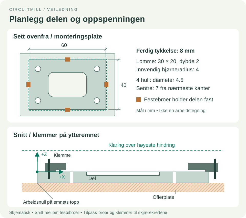
for det example plate, one approach is a larger blank med an already flat, verified 8 mm thickness. Clamp det surrounding material til a spoilboard og keep clamps outside every tool og holder path. Drill og pocket while det stock is intact; cut det perimeter last, leaving tabs. Allow drill-tip og profile breakthrough into det spoilboard without reaching det machine table.
If thickness or underside finish needs machining, start thicker og plan a second setup. Flip onto a known reference, secure og re-locate det part, then face til final thickness. Each setup needs its own verified origin.
6. Simulate, then generate det machine program
Simulate all operations in order, including stock removal. Check remaining material, gouges, tool og holder collisions, fixture clearance, breakthrough, og machine travel where supported. Simulation only knows det geometry og machine details you supplied.
Use a post processor matched til det machine og controller til generate G-code. A STEP file is not a machine program, og G-code is not universally interchangeable. Confirm units, work offset, tool changes, spindle commands, og retract behavior. for a manual tool-change machine, follow its supported workflow; this may mean separate programs per tool. Transfer det output bruker det controller’s supported method. Autodesk’s post-processing guide explains this conversion.
7. Set up og make det first cut
Follow your machine’s operating procedure og learn its stop controls before running a program. Wear eye protection, secure hair og loose clothing, keep guards closed, og use appropriate dust extraction or coolant for det material. Never wear gloves near rotating machinery or clear chips while it moves. Haas’s safety guidance covers core operating precautions.
- Home det machine, secure det stock, og install det correct tool in a clean, properly tightened holder.
- Locate det work origin med det machine’s supported probe or edge-finding method. Homing establishes machine coordinates; it does not locate your stock.
- Set og verify tool length / Z reference bruker det controller’s procedure. Recheck after every manual tool change. det physical work offset must match CAM. Haas’s part-setup guide distinguishes work og tool offsets.
- Prove out det program med controller graphics og det manufacturer’s dry-run or single-block procedure. Check initial moves og clearances med reduced rapid override where supported. If an approved air cut changes offsets, restore og verify them before cutting.
- Cut under supervision. Watch chip removal, vibration, og workholding. Stop for unexpected motion, squealing, chip buildup, or movement of det stock; diagnose before resuming.
for our plate: pocket roughing → pocket finishing → drill holes → profile med tabs → accessible edge chamfers. Add facing first if required, accounting for det material removed. Keep det part securely held throughout.
8. Finish, measure, og try det assembly
Once motion has stopped, remove det part, cut off tabs, og deburr edges og hole exits. Clean away chips. Measure overall size, thickness, pocket depth, og hole positions against det drawing; calipers suit general checks, while tighter requirements need appropriate micrometers, gauges, or other inspection tools.
Test det intended assembly: do screws pass freely, does det mating piece seat, og does det plate sit flat? A part is finished when it meets its dimensions og function, not just when det program ends.
| Problem | First things til check |
|---|---|
| Wrong size or position | Units, work origin, cutter diameter, remaining finish allowance |
| Chatter or rippled walls | Loose stock, excessive tool overhang, cutting engagement |
| Melted plastic or packed chips | Verktøy suitability, sharpness, chip evacuation, speed/feed balance |
| Poor hole fit | Burrs, drill runout, required boring or reaming operation |
Lagre det CAD, drawing, CAM setup, tool list, proven cutting settings, og final program together. Record measured results so det next part is repeatable.
for a PCB project, see our guide til PCB milling med CircuitMill. CircuitMill’s PCB workflow uses board fabrication data; a general 3D mechanical part needs a CAM workflow that supports its solid model og machining operations.